ISO/IEC Guide 51
ISO/IEC GUIDE 51:2014 Safety aspects — Guidelines for their inclusion in standards
provides requirements and recommendations for the drafters of standards for the inclusion of safety aspects in standards
- type A: Fundamental safety standards applicable to all machinery. Type A standards deal with basic concepts, principles for design, and general aspects.
type B: Standards applicable to a wide range of machinery, type B is divided in two categories:
- B1: Specific safety aspects (i.e. safey distance, surface temperature, noise, …)
- B2: Safety related devices (i.e. two-hand controls, interlokcing devices, pressure sentitive devices, …)
- type C: Detailed standards applicable to a specific machine or a particular group of machines
a few pyramids
As can be seen in below table, multiple readers can have multiple understanding of the concepts exposed in IEC Guide 51
| pyramid 1 | pyramid 2 |
|---|---|
 |  |
Standards and best guess classification
ISO
| Standard | Title | Type |
|---|---|---|
| ISO 10218-1 | Robots and robotic devices — Safety requirements for industrial robots — Part 1: Robots | c |
| ISO 10218-2 | Robotics — Safety requirements for robotics in an industrial environment — Part 2: Robot systems and integration | C |
| ISO 12100 | Safety of machinery - General principles for design — Risk assessment and risk reduction | B |
| ISO 14119 | Safety of machinery — Interlocking devices associated with guards — Principles for design and selection | B |
| ISO 13849 | Safety-related parts of control systems Part 1: General principles for design | B |
| ISO 13850 | Emergency stop equipment,functional aspects - Principles for design | C |
| ISO 13851 | Two-hand control devices, functional aspect - Principle for design | C |
| ISO 13855 | The positioning of protective equipment in respect of approach speeds of parts of the human body | C |
| ISO 14121 | Safety Of Machinery - General Principles For Design - Risk Assessment And Risk Reduction | B |
| ISO 26262 | Road vehicles – Functional safety | B |
IEC
| Standard | Title | Type |
|---|---|---|
| IEC 60825-1 | Safety of laser products – Part 1: Equipment classification and requirements | C |
| IEC 60204-1 | Safety of machinery - Electrical equipment of machines - Part 1: General requirements | B |
| IEC 61310-1 | Safety of machinery - Indication, marking and actuation - Part 1: Requirements for visual, acoustic and tactile signals | B |
| IEC 61508 | Functional Safety | A |
| IEC 60825-1 | Safety of laser products – Part 1: Equipment classification and requirement | C |
| IEC 60947-5-1 | Low-voltage switchgear and controlgear - Part 5 Control circuit devices and switching elementsSection one - Electromechanical control circuit devices | C |
| IEC60947-5-8 | Low-voltage switchgear and controlgear. Part 5-8 : Control circuit devices and switching elements. Three-position enabling switches | C |
| IEC 61946-1 | Safety of machinery - Electro-sensitive protective equipment - Part 1: General requirements and tests | B |
| IEC 61946-2 | Safety of machinery - Electro-sensitive protective equipment - Part 2: Particular requirements for equipment using active opto-electronic protective devices (AOPDs) | B |
| IEC 61946-3 | Safety of machinery - Electro-sensitive protective equipment - Part 3: Particular requirements for active opto-electronic protective devices responsive to diffuse Reflection (AOPDDR) | B |
| IEC 61946-4-3 | Safety of machinery - Electro-sensitive protective equipment - Part 4-3: Particular requirements for equipment using vision based protective devices (VBPD) - Additional requirements when using stereo vision techniques (VBPDST) | B |
| IEC 61946-5 | Safety of machinery – Electro-sensitive protective equipment - Part 5: Particular requirements for radar-based protective Devices | C |
| IEC 62061 | Functional Safety for machinery (SRECS) | B |
| IEC 62471 | Photobiological safety of lamps and lamp systems | C |
| IEC TS 62998-1 | Safety of machinery Safety-related sensors used for the protection of persons | C |
EN
| Standard | Title | Type |
|---|---|---|
| EN 61810-3 | Electromechanical elementary relays. Relays with forcibly guided (mechanically linked) contacts | C |
| EN 50205 | Superseded, Withdrawn by EN 61810-3 | C |
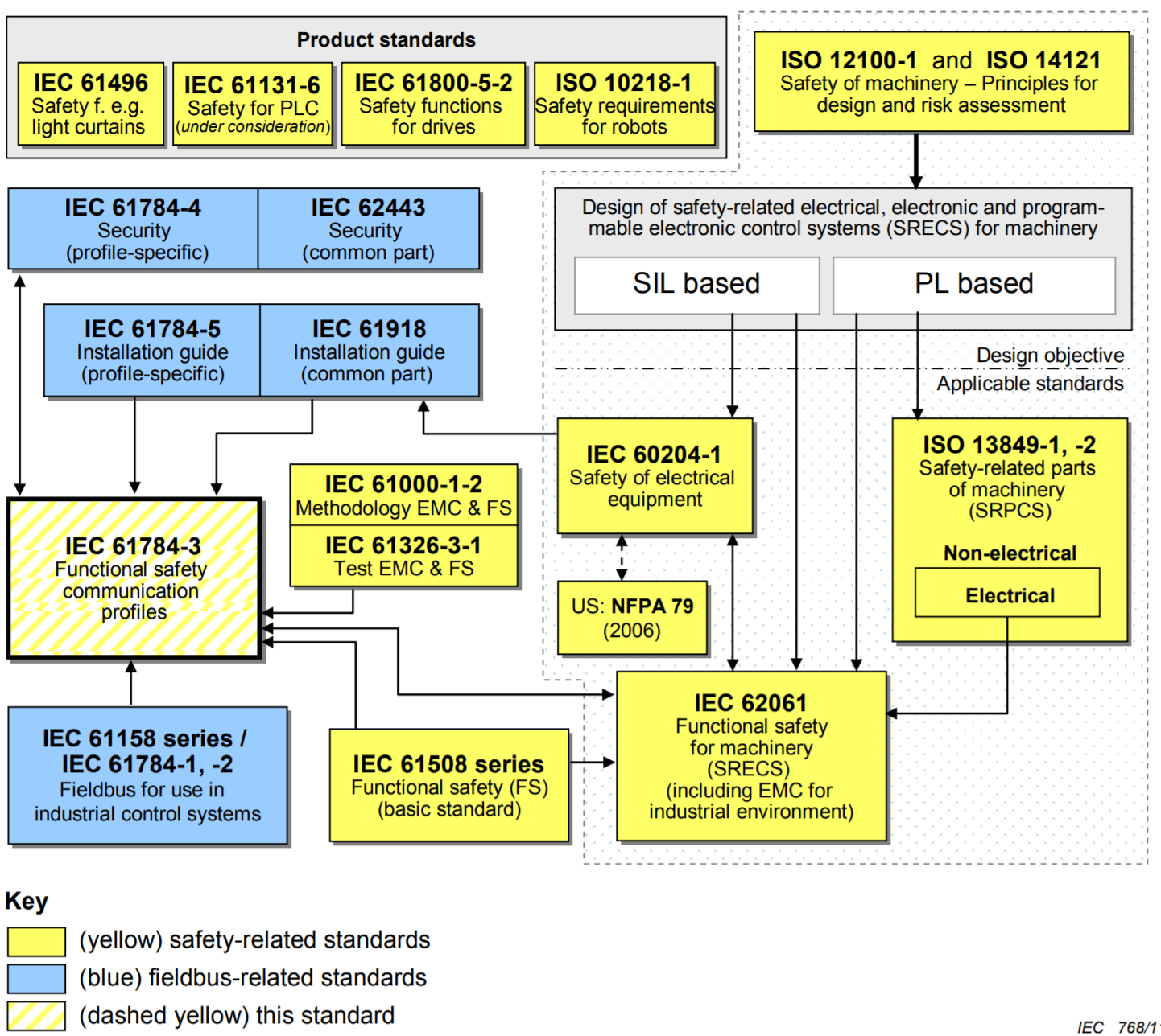
Example of safety for communication
Safety Glossary
Switch/Relay Terminology
Rated Operating Voltage (Ue) (IEC60947-1): The rated operational voltage (Ue) of equipment is the voltage applied to equipment, and is combined with the rated operational current (Ie) as references for utilization categories (i.e., AC-15).
Rated Operating Current (Ie) (IEC60947-1) The rated operational current (Ie) is the current applied to equipment.
Conventional Free Air Thermal Current (Ith) (IEC60947-1) The conventional free air thermal current (Ith) is the maximum test current used by the manufacturer for temperature-rise tests on unenclosed products in free air.
Conventional Enclosed Thermal Current (Ithe) (IEC60947-1) The conventional enclosed thermal current (Ithe) is the test current stated by the manufacturer to be used for temperature-rise tests on products mounted in a specified enclosure. The value of the current must be greater than that of the rated operational current (Ie).
Rated Impulse Withstand Voltage (Uimp) (IEC60947-1) The rated impulse withstand voltage (Uimp) is the peak value for an impulse voltage of prescribed form which equipment is capable of withstanding without failure and to which clearance values are referred.
Rated Insulation Voltage (Ui) (IEC60947-1) The rated insulation voltage (Ui) is the maximum operating voltage that can be withstood without damage. It is the reference voltage for dielectric strength tests and creepage distance for insulation material. The maximum value of the rated insulation voltage (Ui) must be greater than that of the rated operating voltage.
Switching Overvoltage (IEC60947-1) The switching overvoltage is the maximum reverse voltage that occurs with load switching. It must never exceed the rated input withstand voltage (Uimp).
Rated Conditional Short-circuit Current (IEC60947-1) The rated conditional short-circuit current is the current stated by the manufacturer that a product can withstand provided the product is protected by a device (10-A fuse model gI or gG/IEC60269 for the D4BL) that is designated by the manufacturer under conditions specified by related product standards.
Utilization Category for Switching Capacity (IEC60947-1)
Utilization Category for Switching Elements (Classified by switching path and current.)
| Current | Category | Main application | | AC |AC-12 | Control of resistive loads and solid-state loads with photocoupler isolation. | | |AC-13 |Control of solid-state loads with transformer isolation. | | |AC-14 |Control of small electromagnetic loads (≤72 VAC). | | |AC-15 |Control of electromagnetic loads (>72 VAC). | | DC |DC-12 |Control of resistive loads and solid-state loads with photocoupler isolation. | | |DC-13 |Control of electromagnetic loads. | | |DC-14 |Control of electromagnetic loads with economic resistors in the circuit. |Safety Switch Categories According to GS-ET-15, safety switches equipped with positive opening mechanisms are classified in category 1 or 2 according to functional differences.
Category 1 A safety switch falls under category 1 if the switch mechanism and actuator are of monoblock construction physically and functionally, and the safety function is activated by actuator operation.
Category 2 A safety switch falls under category 2 if the switch mechanism and actuator are not of monoblock construction and the safety function is activated when the actuator is separated from the switch mechanism.
Sensor Terminology
Type 4 (IEC61496-1) Type 4 safety devices satisfy category 4 requirements prescribed in EN954-1.
Electro-sensitive Protective Equipment (ESPE) (IEC61496-1) ESPE equipment electrically detects people and outputs a control signal for their protection.
Active Opto-electronic Device (AOPD) (IEC61496-2) AOPD protective devices are electro-sensitive protective devices that operate on the principle of detection by emitted and received light.
Protective Height (IEC61496-2) The protective height is the range within which objects can be detected. The height is the length from the first optical beam to the last optical beam.
Response Time (IEC61496-1) The response time is the maximum amount of time it takes from the moment someone is detected in the detection zone until the output turns OFF. The time it takes to turn output ON again once it goes off is also listed in catalog specifications mainly for system design.
Muting Function (IEC61496-1) The muting function temporarily disables the detection function. In that case, the protective equipment remains ON regardless of whether someone enters the detection zone or not. F3SN-A models do not have the muting function. The muting function can be added by connecting the F3SP-U2P Muting Controller. The muting function can also be added to the F3SJ-A by mounting the F39-CN6 Muting Cap.
Test Rod or Test Piece (IEC61496-2) A test rod is an opaque rod equivalent to the smallest detectable object. It is an accessory that is used to check the detection performance of area sensors.
Minimum Distance from the Detection Zone to the Danger Zone (EN999) The safety zone is the minimum distance that must be allowed from hazardous parts of machinery to the protection equipment. It is prescribed so that machinery will turn OFF before someone entering the detection zone of the protection equipment reaches hazardous parts of the machinery.
Light Beam Axis (IEC61496-2) The imaginal line that top beam and bottom beam of light curtain is connected. It is the reference line that is used to measure the Safety distance from hazardous parts of machinery to the light curtain. The axis is marked by the light beam axis line mark on the indicator section of F3SN-A models.
Effective Aperture Angle (IEC61496-2) The effective aperture angle is the angle to which area sensors must be rotated to switch the output from ON to OFF. Measurements can be taken in two directions with lateral rotation as long as the rotation follows the axis formed by the light beams.
Lock Out (IEC61496-1) A lock out disables normal operation and it occurs when the output is forced OFF. When F3SJ/F3SN control output remains OFF because self-diagnosis results have determined that operation cannot be resumed as a result of a fault, this is called a lock out.